Devices Measuring Alternating Current
INTRODUCTION
The better day to all the audience of the channel and to all the followers of the Blog La Bitácora. In our first video tutorial we will touch on the issue of measurement, as we mentioned the purpose of this space is to make low cost projects, but that can generate a positive impact on our work or production process.
EWe have to start, little by little, the first projects are basic to go up in the scale or dimension of the project. Let's first approve of tools that will serve us later to make them. History gives us a teaching of these achievements, first the wheel then the vehicles; To learn to fly, first the man had to know the principles of aerodynamics and handling of materials. This is how everything starts by taking small steps at the beginning, which are basic to forge the future of what we will become.
IWe enter into matter; today I bring two elements or devices that were created with the purpose of helping control processes, the first step to be able to exercise control is to measure the direct or indirect variables that affect the product or final result.
THE VARIABLE TO MEASURE: ALTERNATING CURRENT.
Device 1: MEASURER – SENSITIVITY AMPLIFIER
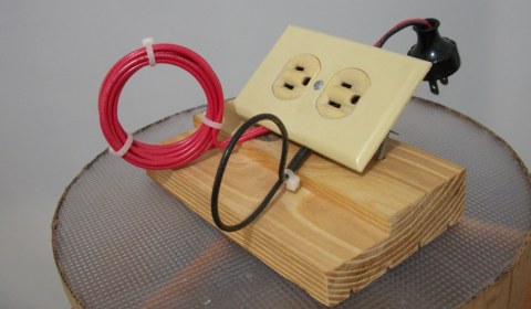
IWe designed this contraption after seeing an article on the Internet about 2 years ago, where they explained how to measure small currents with a voltiamperimetric clamp of low sensitivity; the procedure consists of winding the wire or cable where the current that is to be measured is passing and then reading the voltiamperimetric clamp dividing it by the number of turns made on the wire or cable, well I did the test and it is also applicable for equipment more accurately, apply this knowledge and I made this prototype, then I will show you the final design, the idea is to first make devices that we can try and eventually improve their features and design.
IThe device has 2 wire turns # 12 AWG each turn of wire uses this gauge. The measuring range of the devices is directly related to the wire gauge used, do not exceed the capacity of the instrument! It can be dangerous and cause accidents.
Purpose:
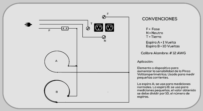
TSpiral A has a single turn of wire.
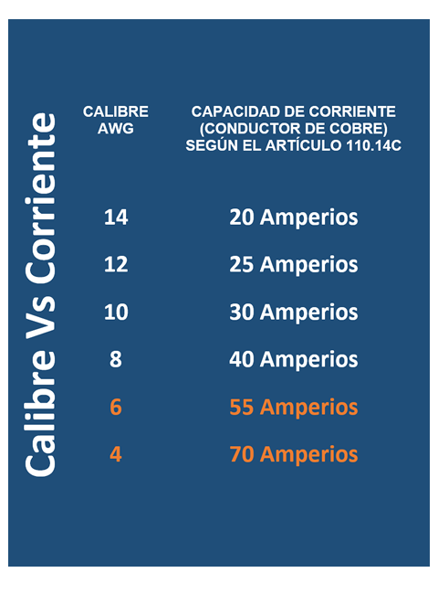
It serves to measure the current in a normal way with a voltiamperimetrica clamp, Annex Table of Current Vs Diameter Wire.
IIt is used to amplify the sensitivity of the clamp, it measures small intensities with a voltiamperimetrica clamp, the registered value must be divided by the number of turns that the coil has.
IA wide-range instrument (Amperage) can be used to measure current that would otherwise have to be tested with a multimeter; with the security of not having to open the circuit to place your tester in series; making measurement a safe and fast job.
T Next I leave the construction scheme of the device.
PROCESS MEASUREMENT
- Connect the object to be tested on the test socket.
- Place the coil with which you want to work between the jaws of the clamp.
- Connect the device to the outlet or energize the circuit.
- Turn on the equipment on which you want to perform the measurements.
- Take the readings; remember to write down the values; Take the peak values, for protection calculations, if applicable.
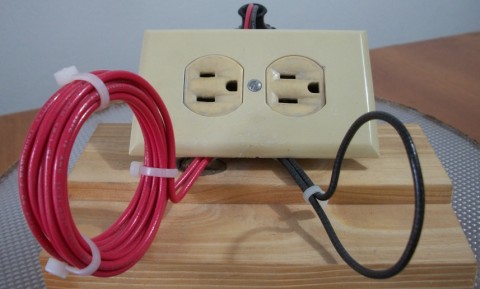
Device 2: MEASURER CURRENT WITH MULTIMETER

IThe second device is used to measure the intensity consumed by a device, instrument, household appliance or tool with the multimeter. This process is done in a simple and safe way without having to intervene the object to make the measurement.

PROCESS MEASUREMENT
- Connect the red probe of the multimeter to point A, adjust the screw.
- Place the black probe of the multimeter in point B, adjust the screw.
- Plug the object to be tested into the test socket; in the photo is orange
- Connect the device to the outlet or energize the circuit.
- Turn on the equipment on which you want to perform the measurements.
- Take the readings; remember to write down the values; Take the peak values, for protection calculations, if applicable.
Note: the current is measured in series; check that the probes are on the tester terminals indicated to measure current. Both devices are used to measure alternating current.
Materials Device 1
1 Double socket with ground pole
1 Plug
2 Screws.
Small plastic ties
Piece of wood of 17.5 cm x 10 cm.
3 mt. of copper wire # 12 AWG.
1 splice tab 35 amps minimum.
Materials Device 2
1 Extension socket with pole to earth (optional)
1 Plug with ground pole (optional)
Small plastic ties
2 mt. of copper wire # 14 AWG. Duplex for single circuit or Trifilar for circuit with ground pole (optional)
2 junction card 25 amps minimum.
BWell there is nothing left to say that hands-on, make the 2 devices does not take more than 2 hours including purchases if you have a hardware store near or you have materials you can use.
RPerform tests, compare the measurements using the two devices, measurements with multimeter and clamp, cross the information with the plate of the instrument or equipment to be measured.
TReady we have our first laboratory devices ... wait for the next project see you soon.
Leave a Reply